In one of my earlier posts I mentioned that I get a loft of ‘carpet drift’ with Tricky. By this, I mean instead of travelling in a straight line, the friction of the carpet pile drags the wheels causing the robot to drift left and right. In some cases, it will steer in one direction fairly constantly, in others the robot will bob between left and right quite randomly.
One simple solution to reduce this is to make the robot
front wheel drive (ie power the front wheels, not the back). But this does not eliminate
the drift totally, and there may be specific design reasons for having a rear
wheel drive.
Another way to overcome this is to create a program that
knows what direction the robot should be travelling in and what
direction it is actually travelling in (using the onboard motion
sensor). And this is where Proportional–Integral–Derivative (PID) control comes
in. This is a calculation that aims to
correct the error (the difference between the ‘should’ and the ‘actual’
directions) as quickly and as smoothly as possible.
Each of these 3 elements (P, I and D) are used to calculate the
most efficient route to the solution – in this case travelling in the right
direction.
Proportional
Imagine you had to walk along a straight line on the
pavement, blindfolded, with only the verbal instructions of a friend to correct
you if you went wrong. Let’s say you drift off the line slightly to the left,
so your friend tells you to turn right. If you turned 90 degrees and continued
walking, you would immediately cross the line to the other side and would need
another instruction from your assistant. If you continue to turn 90 degrees
each time you would zig-zag back and forth over the line, probably never
following smoothly. However, if you had only turned a couple of degree (a
proportional amount) then you would probably be heading back towards the desired
path.
For our robot this is easy – we can measure exactly the
current direction and compare this to the initial direction to calculate the
angle needed to correct the error. The calculation to work out how much we
should turn is:
(desired angle – actual angle)
* proportional amount
The proportional amount is arbitrary and will be different
depending on the situation. For example, I initially set the proportional
amount (often referred to as Kp) for my vehicle to 1. This was not enough, the pile in the carpet
was causing the vehicle to drift more that it was being corrected by the
program. I then tried 90 and as in the example above. This was too much causing
the robot to zig-zag left and right erratically. After a bit of ‘higher than,
lower than’ I finally settled on 10 for the Kp. (I would say that the carpet
has a standard pile, so this might be a good starting point for your vehicle.)
Also consider that in this situation the input and output
are in the same units – I am detecting the error in degrees and correcting the
movement by altering the direction in degrees. Often this will not be the case.
For example, if you were programming a line following robot, the input would be
the measurement of reflected light from the sensor and the output would be degrees
of steering for the robot. Click to watch this great video that shows how to
program this for the EV3. It also explains PID really well: https://www.youtube.com/watch?v=AMBWV_HGYj4
)
Build Instructions
For this experiment I created a very simple rear wheel drive
bot, with lower small front wheels in an attempt to add more weight to the
front to increase the drag and accentuate the drag issue. Click here for the
build instructions.
The Problem
The following video shows the result of the bot trying to
drive forward in a straight line. I used the Scratch blocks below for a
simple drive program.

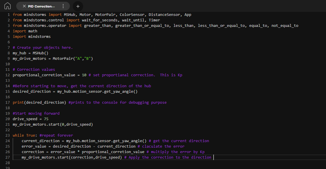
Programming a solution
The algorithm I came up with for the Python program was:
1) Detect the current yaw angle of the vehicle and store it as
the ‘desired angle’ (this is the direction the hub is currently pointing)
2) Start to move forward
3) Detect the current value of the yaw angle
4) Do the calculation (desired angle – actual angle) *
proportional amount
5) Move the vehicle forward at the angle calculated above
6) Repeat steps 3-6
Applying the code to the robot
The following video shows the result of the above code, from
the same starting point. Towards the end of the video you can see the Lego astronaut
at the left – this is where the original robot (no PID) finished. I tested with
and without PID several times and got very similar results.
As always, try to type in the code above, but if you cannot get it to work, click here to download it.
This code seems to give the desired result and I wondered if
I needed to add the I and D into the PID calculation? For completeness I will
look at Integral and Derivative in a future post.
Comments
Post a Comment